Operating requirements
- Airflow and external static pressure
- Cooling / heating capacity
- Entering and leaving air conditions
- Chilled-water supply / return temperatures
- Filtration and moisture duties

Air-side equipment / Modular AHU
Modular air handling units for project-specific air treatment. Start with your airflow, duty conditions and available space. We review the equipment configuration against those requirements.
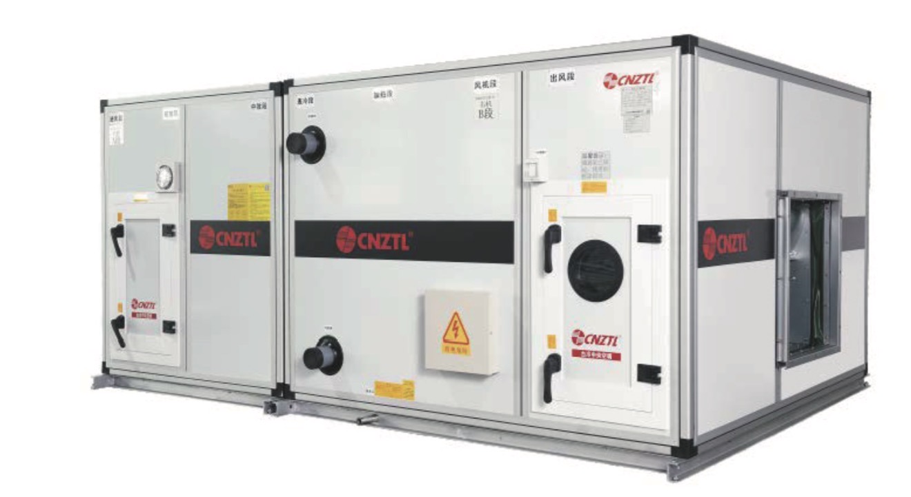
See how the equipment is organised
Explore a typical section sequence. Each block describes a selection decision, not a fixed standard configuration. Click a section for the information we need.
Confirm fresh-air and return-air quantities, inlet positions and damper requirements. The mixing arrangement follows the air path specified by the project designer.
Concept diagram only. Section order, access sections, drainage, filtration stages and equipment lengths require project-specific confirmation. It is not a fabrication or installation drawing.
Configuration, clearly defined
A component option is not a standard inclusion. Brand, model, performance and quantities are recorded in the final technical submission and quotation.
| Assembly | Configuration discussion | Information to confirm |
|---|---|---|
| Casing & access | Panel construction, material, service access and installation orientation | Site conditions, corrosion requirements, access side and available footprint |
| Coil sections | Cooling and heating arrangements matched to the specified duty | Entering/leaving air, water temperatures, capacity and allowable pressure drop |
| Fan assembly | Fan type, motor and control options, including EC options for review | Airflow, external static pressure, power supply and control interface |
| Filtration | Filter stages, grades, access and replacement arrangements | Required classification, clean/dirty pressure basis and service space |
| Humidity & controls | Humidification options and controls to suit the equipment duty | Required moisture duty, utilities, sensors, control sequence and panel scope |
| Delivery configuration | Unit split, module identification, export packing and transport interfaces | Access restrictions, assembly arrangement, destination and agreed trade term |
Airflow and capacity ranges, efficiency, noise, casing classifications and delivery dates are stated only when supported by the applicable equipment selection and confirmed documents.
Equipment selection starts here
Already have an AHU schedule? Send it with the drawings. If only the room area or target temperature is available, first confirm who is responsible for the project cooling-load calculation and system design.
From configuration to manufacture
Equipment selection, physical construction and packing each need their own information. These Taile photographs show manufacturing activity; they do not establish a specific model's performance or test result.
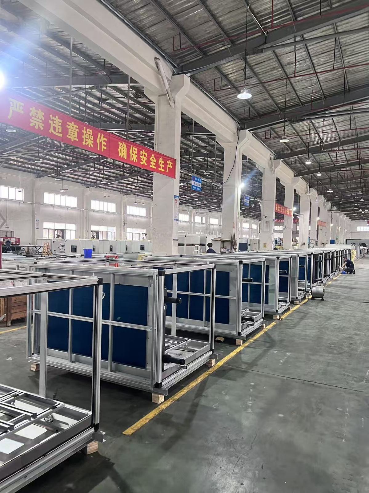
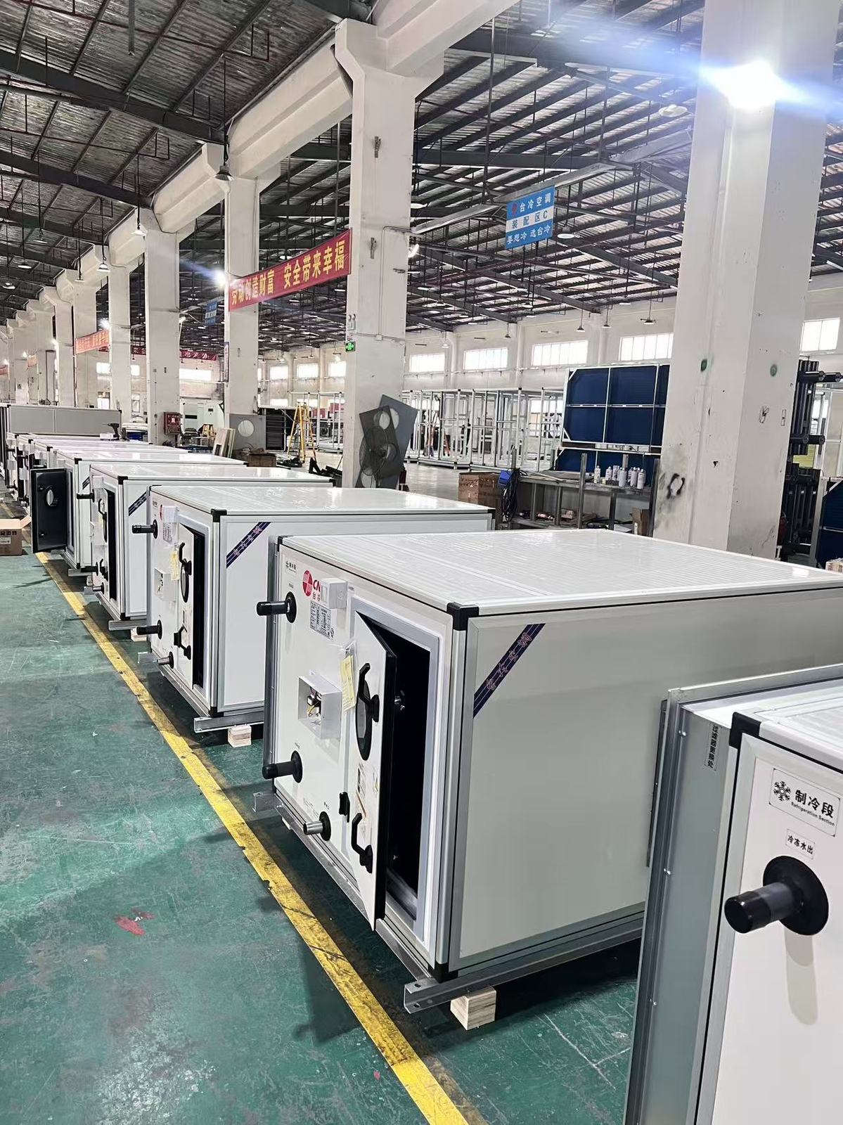
A defined supply boundary
Our scope is equipment manufacturing and supply. Equipment-related technical support and any attendance must be explicitly defined and commercially agreed.
For large units, module splits, piece counts, gross weights and container arrangements depend on final design and packing confirmation. A preliminary estimate is identified separately from a final shipping document.
Useful documents, attached to the equipment
Selection and commercial details should travel together. Project-specific data sheets, drawings and component schedules are issued after review of the equipment requirements.
Talk equipment with Kalyn
Send the equipment requirements and project location. We will check whether the proposed duty is within our supply scope and identify the information needed for a quotation.